In the second third of the manometer scale. What does a pressure gauge measure and what pressure does it show. Residual pressure is determined by the formula
0,6; 1,0; 1,6; 2,5; 4,0
60 100 160 250 400
600 1000 1600 kgf/cm 2
Selection of pressure gauges according to the permitted
operating pressure
The scale of the manometer must be marked with a red line corresponding to the permitted working pressure.
The red line is placed on 2/3
manometer scales.
Rice. 2.5. red line gauge
If it is necessary to select a manometer according to the permitted pressure P diss, then (2.8)
and select the nearest higher value from the gauge series.
Example
Select the scale of the pressure gauge, if R razr = 10 kgf / cm 2
![]()
There is no such scale, so the scale is selected from 0 to 16 kgf / cm 2 .
Electrocontact pressure gauges
They have an electrical contact device that is triggered when a predetermined pressure is reached and sends a pulse to signaling devices.
The manometer is supplied with two control arrows with contacts. The control arrows are set to "max" and "min" pressure, and the arrow of the device, which carries the contacts, moving, gives a signal if the pressure has reached the values set by the control arrows.
EKM - electrocontact pressure gauge (used to signal parameters in explosion-proof rooms);
EKV - electrocontact vacuum gauge;
VE-16rb - electrocontact pressure gauge, explosion-proof design.
Bellows pressure gauges
MSS - self-recording bellows manometer, designed to measure pressure and record it on disc chart paper.
The principle of operation of the MSS is based on balancing the measured pressure with the force of elastic deformation of the bellows.
The measured pressure enters through the fitting into the cavity of the bellows mechanism and causes the bottom of the bellows to move, which is transmitted through the transmission mechanism to the pen of the device. The internal cavity of the bellows is connected to the atmosphere.

Fig.2.6 Bellows pressure gauge MCC
The pressure measurement limit depends on the wall thickness, the size and number of corrugations of the bellows, as well as on the metal from which it is made.
Bellows instruments are divided into indicating and self-recording. They can be with a pneumatic output signal, with an alarm device, with a record of one or 2 pressures, with a pneumatic control device.
MCC pressure gauges are used for direct pressure measurement and as secondary instruments. If the MSS is used for direct pressure measurement, then they are connected directly to the pipeline or apparatus.
They have the following measurement limits:
0 ¸ 0.25; 0 ¸ 0.4; 0 ¸ 0.6; 0 ¸ 1; 0 ¸ 1.6; 0 ¸ 2.5; 0 ¸ 4 kgf/cm 2 .
If MSS is used as a secondary device, then they are connected to the apparatus or pipeline through the primary device.
In this case, MSS have measurement limits from 0.2 to 1 kgf / cm 2 .
In self-recording pressure gauges, the rotation of the diagram can be carried out using a clockwork or a synchronous motor. Clockwork devices are used in explosive areas.
The diagram shows a time reference, which can be used to determine the measured pressure relative to the operating time of the process equipment. The disk chart paper makes one revolution per day, then it is replaced with a new one.
Within the framework of this article, the advantages and disadvantages of the most common methods for placing the red arrow, as well as the compliance of these methods with regulatory documents and the needs of enterprises that operate pressure gauges, will be considered.
The root of the problem
A red mark must be present on the pressure gauge dial - this provision is common to all standards that regulate the operation of pressure devices.
Specialists responsible for compliance with production standards are often not aware of the possible options for applying a red mark and, receiving devices with a missing arrow, try to implement this mark on their own when installing pressure gauges. As a rule, the problem is solved with the help of simple technologies and using improvised materials, which does not always correspond to operational needs, and does not fully ensure the stability of the mark position during the life of the device.
Regulations that are guided by the inspection bodies
To begin with, I would like to dwell on the standards that engineers follow when installing pressure gauges, some provisions are common to all devices operating under pressure, and some are mandatory for use only in some sectors of the economy.
RULES FOR THE DEVICE AND SAFE OPERATION OF VESSELS WORKING UNDER PRESSURE PB 03-576-03
5.3.4. On the pressure gauge scale, the owner of the vessel must put a red line indicating the working pressure in the vessel. Instead of a red line, it is allowed to attach a metal plate to the pressure gauge case, painted red and tightly adjacent to the pressure gauge glass.
SAFETY RULES FOR THE OPERATION OF MAIN GAS PIPELINES.
6.41. “... Pressure gauges on gas pipelines and devices with a pressure equal to or more than 10 MPa must have rubber plugs (plugs) to protect the body from destruction in the event of gas passing into the Bourdon tubes or a Plexiglas protective device that protects the maintenance personnel from splinters in case of destruction."
SAFETY REGULATIONS IN THE OIL AND GAS INDUSTRY.
5.1.19. “Pressure gauges must be selected with such a scale that the working pressure measurement limit is in the second third of the scale. On the dial of pressure gauges, a red line must be applied or a red plate must be fixed on the glass of the pressure gauge through a division of the scale corresponding to the permitted working pressure. ... "
STO GAZPROM 2-3.5-454-2010.
13.1.28 "... On the scales of stationary indicating measuring instruments, a red line is applied corresponding to the maximum allowable value of the measured value."
RULES FOR TECHNICAL OPERATION OF MAIN GAS PIPELINES VRD 39-1.10-006-2000
9.1.29. "... On the scales of stationary measuring instruments, a red line should be applied, corresponding to the limit value of the measured value."
9.4.18. On the scales of the most important stationary measuring instruments that do not have the appropriate limiting indicators, red risks of the limit values of the controlled parameter should be applied. The list of such devices is approved by the chief engineer of the facility.
REGULATIONS FOR THE TECHNICAL OPERATION OF GAS DISTRIBUTION STATIONS OF MAIN GAS PIPELINES VRD 39-1.10-069-2002
3.1.48. All pressure gauges must be marked with a red mark indicating the maximum allowable working pressure of the gas.
NAOP 1.1.23-1.02-83 RULES OF OPERATION AND SAFETY OF MAINTENANCE OF AUTOMATION, TELEMECHANIZATION AND COMPUTER EQUIPMENT IN THE GAS INDUSTRY
3.92. On the scales of stationary electrical measuring instruments, a red line should be applied corresponding to the nominal value of the measured value.
In addition, similar provisions on the presence and methods of implementing the "red mark" are contained in the following resolutions of the Gosgortekhnadzor of Russia:
dated 27.05.03 N 40 approved the Safety Rules for facilities using liquefied hydrocarbon gases (PB 12-609-03), registered by the Ministry of Justice of Russia on 19.06.03, registration N 4777;
dated 04.03.2003 N 6 approved "Safety Rules for the operation of automobile filling stations of liquefied gas" (PB 12-527-03), registered by the Ministry of Justice of Russia on 25.03.2003, reg. N 4320 and officially published in the Russian newspaper, N 120/1, 06/21/2003 (special issue);
dated 18.03.2003 N 9 approved "Safety Rules for Gas Distribution and Gas Consumption Systems" (PB 12-529-03), registered by the Ministry of Justice of Russia on 04.04.2003, reg. N 4376, officially published in the Russian newspaper, N 102, 05/29/2003.
General provisions and nuances of the Safety Rules
The presented standards somewhat contradict each other regarding the method of applying the red mark, but common to all standards is the indication that this mark must be present on the pressure gauge.
Some provisions say that the arrow must indicate the nominal working pressure, while other rules say that there is an arrow at the maximum allowable pressure value;
The same differences exist in the definition of the labeling method. So, "SAFETY RULES IN THE OIL AND GAS INDUSTRY" say that the pointer on the pressure gauge should be made in the form of a red line or a plate attached to the body. In other regulations, it is only said that the red label should simply be present, without specific indications of what form this label should have.
Artisanal solutions
It must be emphasized right away that any solution of this kind can potentially become a source of trouble for the inspection authorities, not to mention the fact that such an approach is rather poorly suited to the needs of production. Handicraft methods include:
Drawing a line with paint on the protective glass of the manometer;
The red line is made in the form of a sticker (polymer film), applied to the body and glass;
The arrow is made in the form of a hard lining on the pressure gauge body, without secure fastening (for the possibility of changing its position)
The red line looks like a metal plate attached to the body
Drawing a line with paint or in the form of a sticker on the case and glass
These solutions can, in extreme cases, serve as a temporary measure, since they have a number of significant drawbacks. For example, paint applied directly to protective glass may be subject to damage due to moisture, the line may be accidentally erased during maintenance of the equipment. The same applies to the polymer film from which the sticker is made. When operating pressure gauges in free access conditions, anyone who is nearby can change or damage the indicator, such a solution does not imply any anti-vandal protection.
In addition, if the arrow is applied with paint, when changing the operating parameters of the equipment, it may be necessary to change the position of the arrow, for which it will need to be erased or painted over. Abrasion can damage the paint layer applied by the manufacturer, and this leads to corrosion and premature gauge failure. If the arrow is made in the form of a hard pad that is not fixed to the body, this pad may also be shifted during maintenance.
The red line looks like a metal plate attached to the body
The arrow in the form of a metal platinum, attached to the body with screws, welded, eliminates both accidental and intentional displacement. However, this also determines the impossibility of applying the method under conditions of periodic changes in the technological process, when the position of the arrow must be changed. In addition, the disadvantage is the possibility of a violation of the tightness of the device, which can occur when drilling holes for screws (or as a result of burning by the electrode during welding).
Ready solutions
The methods proposed by the device manufacturer themselves are much more reliable. When choosing a pressure gauge, the responsible employee can be guided solely by criteria related to production needs and be absolutely sure that the instruments comply with the Safety Rules. Instrument manufacturers can offer the following solutions:
The red line looks like a metal plate attached to the case;
The red line looks like a metal or plastic plate attached to the body with a non-stationary mount;
The red line looks like a metal plate fixed on a clamp;
The red line is made in the form of an arrow mounted on the pressure gauge mechanism itself (on the same element as the arrow indicating the actual pressure).
The red line is applied directly to the dial
The nominal (or maximum possible) pressure indicator is applied with red paint on the dial at the factory. This solution is quite reliable, since it fully complies with the expected operating conditions of the pressure gauge. It is impossible to accidentally remove or change the pointer, since the device is sealed and a special tool is needed to open the protective glass.
Such a solution can be applied if the indicator of the working (maximum) pressure is known in advance (it is regulated by the technical conditions that are mandatory). On the other hand, such a solution cannot be applied if the technical conditions (pressure levels) are determined independently in production. It would be necessary to remove the initially applied line and apply a new one - this is a rather laborious process, especially under the condition of permanent changes in the technological process under the influence of various factors.
The red line looks like a metal or plastic plate attached to the case with a non-stationary mount
To implement such a solution, a spacer mechanism or plastic clamps are used, this allows you to change the position of the pointer as needed, moreover, you can do this right during operation. However, this advantage also has a downside - the pointer can be changed by accident, by vibration, during equipment maintenance, or intentionally by a person who wants to harm.
The solution can be applied only if the listed factors are absent - maintenance is performed quite rarely, there are no vibrations, and a limited circle of people has access to pressure gauges.
The red line looks like a metal plate attached to a clamp
This method of pointer installation is more reliable than the above-described fixing mechanism on the clamps, and also allows you to quickly change the position of the pressure indicator. The advantage is the need to apply certain efforts for this - it is necessary to unwind the clamp, fix the arrow in a new position and fix the structure with a tool.
In this case, we are not talking about an accidental change in the position of the pointer, neither the vibration of the device, nor the careless movements of the personnel can cause the pointer to move. However, complete anti-vandal protection in this case is also absent; if the pressure gauge is operated in an open area, the arrow may be broken off by unauthorized persons out of hooligan motives.
The red line is made in the form of an arrow, which is part of the design of the pressure gauge
This is the most reliable option for complying with the requirements of the regulations, since it fully provides protection against possible displacement of the pointer. The pointer can only be accessed by removing the protective glass using a special key. The solution is universal, as it is suitable for operating the device in static pressure conditions, as well as in conditions where technical parameters may change.
The location of the red arrow under the glass makes it impossible to accidentally change the pointer. The versatility of this labeling option lies in the fact that when changing the pressure parameters or operating conditions of the pressure gauge, the responsible employee can change the position of the pointer using a special key. Therefore, a device with a mark in the form of a red arrow under the glass can be used in any production environment.
This approach to the implementation of the red mark is used in devices with a stainless steel case, in pressure gauges, the use of which is a prerequisite for tightness, the method is used in the design of devices with a bayonet shell.
Conclusion
Summing up the description of the ways to implement the "red arrow", it must be said that there is no universal solution that would unequivocally meet all the criteria at once - Safety Rules (requirements of inspection bodies), production needs, price preferences of owners. However, we hope that considering the advantages and disadvantages of each of the methods of applying the "red arrow", as well as the degree of compliance of each of the methods with the standards governing the use of a pressure gauge, will make it easier to choose the best option for each specific case.
A manometer is a compact mechanical device for measuring pressure. Depending on the modification, it can work with air, gas, steam or liquid. There are many varieties of pressure gauges, according to the principle of taking pressure readings in the medium being measured, each of which has its own application.
Scope of use
Pressure gauges are one of the most common instruments that can be found in various systems:
- Heating boilers.
- Gas pipelines.
- Plumbing.
- compressors.
- Autoclaves.
- Cylinders.
- Balloon air rifles, etc.
Outwardly, the pressure gauge resembles a low cylinder of various diameters, most often 50 mm, which consists of a metal case with a glass cover. A scale with marks in pressure units (Bar or Pa) is visible through the glass part. On the side of the housing there is a tube with an external thread for screwing into the opening of the system in which it is necessary to measure the pressure.

When pressurized in the medium being measured, the gas or liquid presses the internal mechanism of the pressure gauge through the tube, which leads to the deviation of the angle of the arrow, which indicates the scale. The higher the pressure generated, the more the needle deflects. The number on the scale where the pointer will stop and will correspond to the pressure in the measured system.
The pressure that a manometer can measure
Pressure gauges are universal mechanisms that can be used to measure various values:
- Excess pressure.
- vacuum pressure.
- pressure differences.
- Atmospheric pressure.
The use of these devices allows you to control various technological processes and prevent emergencies. Pressure gauges designed for operation in special conditions may have additional body modifications. It can be explosion-proof, corrosion-resistant or increased vibration.
Varieties of pressure gauges
Pressure gauges are used in many systems where pressure is present, which must be at a clearly defined level. The use of the device allows you to control it, since insufficient or excessive exposure can harm various technological processes. In addition, excess pressure is the cause of rupture of tanks and pipes. In this regard, several varieties of pressure gauges designed for certain working conditions have been created.
They are:
- exemplary.
- General technical.
- Electrocontact.
- Special.
- Recorders.
- Ship.
- Railway.
Exemplary manometer designed for verification of other similar measuring equipment. Such devices determine the level of overpressure in various media. Such devices are equipped with a particularly precise mechanism that gives a minimum error. Their accuracy class is from 0.05 to 0.2.

General technical apply in general environments that do not freeze into ice. Such devices have an accuracy class from 1.0 to 2.5. They are resistant to vibration, so they can be installed on transport and heating systems.

Electrocontact designed specifically to monitor and warn of reaching the upper limit of a dangerous load that can destroy the system. Such instruments are used with various media such as liquids, gases and vapours. This equipment has a built-in electrical circuit control mechanism. When overpressure occurs, the manometer gives a signal or mechanically turns off the supply equipment that builds up pressure. Also, electrocontact pressure gauges may include a special valve that relieves pressure to a safe level. Such devices prevent accidents and explosions in boiler rooms.

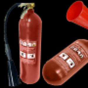
Special pressure gauges are designed to work with a specific gas. Such devices usually have colored cases, rather than the classic black ones. The color corresponds to the gas that the instrument can handle. There is also a special marking on the scale. For example, ammonia pressure gauges, which are commonly installed in industrial refrigeration plants, are colored yellow. Such equipment has an accuracy class from 1.0 to 2.5.

Recorders are used in areas where it is required not only to visually monitor the pressure of the system, but also to record indicators. They write a chart by which you can view the dynamics of pressure in any period of time. Similar devices can be found in laboratories, as well as in thermal power plants, canneries and other food enterprises.

Ship include a wide range of pressure gauges that are weather-sealed. They can work with liquid, gas or steam. Their names can be found on street gas distributors.

Railway pressure gauges are designed to control overpressure in the mechanisms that serve rail electric transport. In particular, they are used on hydraulic systems that move the rails when the boom is extended. Such devices have increased resistance to vibration. They not only endure shaking, but at the same time, the pointer on the scale does not react to mechanical impact on the body, accurately displaying the pressure level in the system.

Varieties of pressure gauges according to the mechanism for taking readings of pressure in the medium
Pressure gauges also differ in the internal mechanism that leads to the removal of pressure readings in the system to which they are connected. Depending on the device, they are:
- Liquid.
- Spring.
- Membrane.
- Electrocontact.
- Differential.
Liquid The pressure gauge is designed to measure the pressure of a liquid column. Such devices operate on the physical principle of communicating vessels. Most devices have a visible fluid level from which they take readings. These devices are one of the rarely used. Due to contact with liquid, their inside gets dirty, so the transparency is gradually lost, and it becomes difficult to visually determine the readings. Liquid manometers were one of the earliest inventions, but are still found.
Spring gauges are the most common. They have a simple design that is suitable for repair. The limits of their measurement are usually from 0.1 to 4000 bar. The sensitive element of such a mechanism itself is an oval tube, which is compressed under pressure. The force pressing on the tube is transmitted through a special mechanism to the arrow, which rotates at a certain angle, pointing to the scale with markings.
Membrane The pressure gauge works on the physical principle of pneumatic compensation. Inside the device there is a special membrane, the level of deflection of which depends on the effect of the pressure generated. Usually, two membranes soldered together forming a box are used. As the volume of the box changes, the sensitive mechanism deflects the arrow.
Electrocontact pressure gauges can be found in systems that automatically monitor pressure and adjust it or signal that a critical level has been reached. The device has two arrows that can be moved. One is set to the minimum pressure, and the second to the maximum. Electrical circuit contacts are mounted inside the device. When the pressure reaches one of the critical levels, the electrical circuit is closed. As a result, a signal is generated to the control panel or an automatic mechanism for emergency reset is triggered.
Differential pressure gauges are among the most complex mechanisms. They work on the principle of measuring the deformation inside special blocks. These elements of the manometer are sensitive to pressure. As the block is deformed, a special mechanism transmits the changes to the arrow pointing to the scale. The pointer moves until the drops in the system stop and stop at a certain level.
Accuracy class and measuring range
Any pressure gauge has a technical passport, which indicates its accuracy class. The indicator has a numeric expression. The lower the number, the more accurate the device. For most instruments, an accuracy class of 1.0 to 2.5 is the norm. They are used in cases where a small deviation does not really matter. The largest error is usually given by devices that motorists use to measure air pressure in tires. Their class often drops to 4.0. The exemplary pressure gauges have the best accuracy class, the most advanced of them work with an error of 0.05.

Each pressure gauge is designed to operate within a specific pressure range. Too powerful massive models will not be able to fix the minimum fluctuations. Very sensitive devices fail or are destroyed when exposed to excessive pressure, leading to depressurization of the system. In this regard, when choosing a pressure gauge, you should pay attention to this indicator. Usually on the market you can find models that are able to record pressure drops in the range from 0.06 to 1000 mPa. There are also special modifications, the so-called draft gauges, which are designed to measure the vacuum pressure to a level of -40 kPa.
PRESSURE MEASUREMENTS
Pressure- one of the most important parameters of technological processes.
By pressure is the ratio of the force acting on the area to the magnitude of the area.
where F- strength;
S- square.
There are pressures:
1) barometric (atmospheric) - P atm;
2) absolute - P abs;
3) excess - P hut;
4) vacuum (vacuum) - P wack
1. barometric pressure is the pressure of the atmosphere surrounding the globe.
2. Absolute pressure is the total pressure under which a liquid, gas or vapor is located.
R abs \u003d R surplus + R atm
3. Overpressure is the pressure above atmospheric pressure.
R izb \u003d R abs - R atm
4. If part of the air is evacuated from a closed vessel, then the absolute pressure inside the vessel will decrease and become less than atmospheric pressure. This pressure inside the vessel is called vacuum.
Vacuum is the lack of pressure to atmospheric pressure.
R vak = R atm - R abs
Rice. 2.1 Types of pressure
The residual pressure is determined by the formula:
R ost \u003d R atm - R vac,
where P atm = 760 mm Hg.
Pressure units
SI unit of pressure- Pascal (Pa).
Pascal is a pressure with a force of 1 N on an area of 1 m 2 .
Off-system units: kgf/cm 2 ; mm water column; mmHg st; bar, atm.
Relationship between units of measurement:
1 kgf/cm 2 = 98066.5 Pa
1 mm w.c. = 9.80665 Pa
1 mmHg = 133.322 Pa
1 bar = 10 5 Pa
1 atm \u003d 9.8 * 10 4 Pa
Classification of instruments for measuring pressure
I. According to the principle of action:
1) liquid;
2) deformation;
3) cargo piston;
4) electrical.
II. According to the type of measured value:
1) pressure gauges- instruments for measuring absolute and gauge pressure;
2) vacuum gauges- instruments for measuring vacuum;
3) combined pressure and vacuum meters- to measure overpressure and vacuum;
4) differential pressure gauges- to measure the difference between two pressures;
5) barometers- to measure atmospheric pressure;
6) pressure gauges(micromanometers) - for measuring small excess pressures;
7) thrust gauges- devices for measuring low rarefaction;
8) thrust gauges- devices for measuring small overpressures and low rarefaction.
Deformation devices
(spring gauges)
In these devices, the pressure is determined by the deformation of the elastic elements.
Fig.2.3 Elastic elements of spring pressure gauges:
a) single-turn tubular spring (Bourdon tube);
b) multi-turn tubular spring;
c) elastic membrane;
d) membrane box;
e) bellows
Pressure gauges with a single-coil tubular spring OBM
OBM-100; OBM-160 - general purpose pressure gauges;
100, 160 - body diameter in mm.
These devices are the most common. Their advantages: simplicity of the device; reliability in work; compactness; large measuring range; low cost.
Operating principle is based on balancing the measured pressure by the force of elastic deformation of the spring.
Under the action of pressure, the cross section of the tube tends to take a round shape, as a result of which the tube unfolds by an amount proportional to the pressure. When the pressure is reduced to atmospheric, the tube returns to its original shape.
Sensing element (SE) The pressure gauge is a single-turn tubular spring, which is a tube bent around the circumference with a cross section in the shape of an oval. The tubular spring is made of bronze, brass or steel, depending on the purpose of the device and the measurement limits.
One end of the tube is soldered into a holder with a fitting, which is designed to connect the pressure gauge to a pressure source.
The other end of the tube is free, hermetically closed.
A rod is attached to the free end of the tubular spring. The other end of the rod is connected to the shank of the gear sector. The shank of the toothed sector has a slot (scene) along which the end of the rod can be moved when adjusting the device.
The toothed sector is held on the axis and engages with a small gear called a pinion. It is rigidly mounted on the axis of the arrow.
To eliminate the "dead motion" of the arrow, caused by the presence of backlash in the connections, the pressure gauge is equipped with an elastic hair of a spiral shape, made of phosphor bronze. The inner end of the hair is attached to the axis of the arrow, and the outer end to the fixed part of the device.
Under the action of pressure inside the tube, its free end moves and pulls the rod along with it. At the same time, the toothed sector and the tribka rotate, on the axis of which the arrow is mounted. The end of the arrow shows the value of the measured pressure on the scale of the device.
Rice. 2.4 Spring gauge:
1 - nipple;
2 - holder;
3 - (body) board;
5 - gear (tribe);
6 - spring;
7- Bourdon tube;
8- sealed end;
9 - gear sector;
10 - arrow;
Depending on the purpose, pressure gauges have the following markings:
MTP, MVTP - vibration-resistant;
SV - ultrahigh pressure;
MTI, VTI - accurate measurements (accuracy class 0.6; 1.0);
MO, VO - exemplary (class 0.4);
MT, MOSH, OBM - technical.
Standard pressure gauge scales
0,6; 1,0; 1,6; 2,5; 4,0
60 100 160 250 400
600 1000 1600 kgf/cm 2
Each vessel and independent cavities with different pressures must be equipped with direct-acting pressure gauges. The pressure gauge is installed on the vessel fitting or pipeline between the vessel and the stop valves.
Pressure gauges must have an accuracy class of at least:
2.5 - at a working pressure of the vessel up to 2.5 MPa (25 kgf / cm 2);
1.5 - at the working pressure of the vessel above 2.5 MPa.
The pressure gauge must be selected with such a scale that the working pressure measurement limit is in the second third of the scale.
On the pressure gauge scale, the owner of the vessel must put a red line indicating the working pressure in the vessel. Instead of a red line, it is allowed to attach a metal plate to the pressure gauge case, painted red and tightly adjacent to the pressure gauge glass.
The pressure gauge must be installed so that its readings are clearly visible to the operating personnel.
The nominal diameter of the case of pressure gauges installed at a height of up to 2 m from the level of the platform for monitoring them must be at least 100 mm, at a height of 2 to 3 m - at least 160 mm. Installation of pressure gauges at a height of more than 3 m from the level of the site is not allowed.
Between the pressure gauge and the vessel, a three-way valve or a device replacing it should be installed, which allows periodic checking of the pressure gauge using a control one.
Pressure gauges and pipelines connecting them to the vessel must be protected from freezing.
The pressure gauge is not allowed for use in cases where:
There is no seal or stamp with a mark on the verification;
Expired due date;
The arrow, when it is turned off, does not return to the zero reading of the scale by an amount exceeding half the permissible error for this device;
The glass is broken or there is damage that may affect the correctness of its readings.
Verification of pressure gauges with their sealing or branding should be carried out at least once every 12 months. In addition, at least once every 6 months, the owner of the vessel must carry out an additional check of the working pressure gauges with a control pressure gauge, recording the results in the log of control checks.
Lecture 11
Marking, installation, fastening of vessels, technical
Documentation
Vessel marking
A label must be affixed to each vessel. For vessels with an outer diameter of less than 325 mm, it is allowed not to install a plate. In this case, all the necessary data must be applied to the body of the vessel by the electrographic method.
The plate must bear:
Trademark or manufacturer's name;
Name or designation of the vessel;
Ordinal number of the vessel according to the manufacturer's numbering system;
Year of manufacture;
Working pressure, MPa;
Design pressure, MPa;
Test pressure, MPa;
Permissible maximum and (or) minimum working temperature of the wall, °С;
Vessel weight, kg.
For vessels with independent cavities with different design and test pressures, wall temperatures, these data should be indicated for each cavity.